
Theory
The 6847 has limited input pins from the main CPU on the Color Computer, and each one has a purpose, at least while the 6847 is actively outputting video. These input pins are A/G (alphanumerics & semigraphics vs. graphics), GM[2:0] (graphics mode), and CSS (color set select). With the many modes and color palette registers available on CoCoVGA, it would be impossible to program each of these during the blanking region by way of these 5 input signals. To enable control of the many CoCoVGA settings from software, these 5 pins are instead used as a combination lock during the blanking region; that is, when the 6847 is not actively outputting video, the combination is applied to inform CoCoVGA to consider the next video frame as register settings, not video.
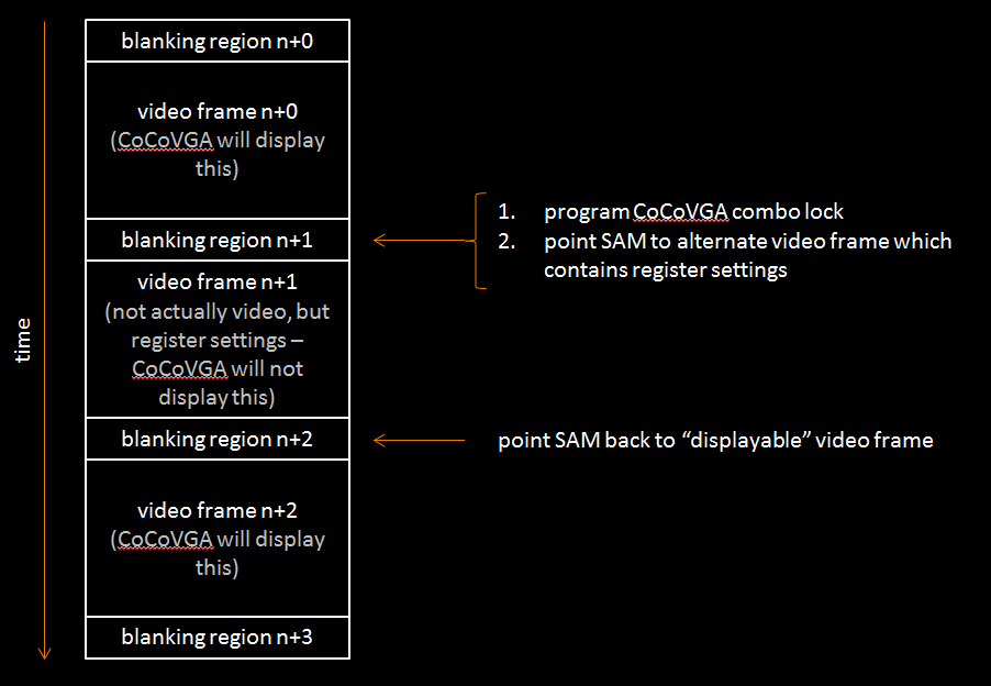
While CoCoVGA is consuming the register settings, it displays the previous video frame. After the single frame of register settings is read and the 6847 is in the following blanking region, CoCoVGA begins working normally again, placing video data into one buffer while displaying the other. (Note that, of course, this causes a 1 frame "flicker" on the TV output since the 6847 has no past video buffer of its own to rely on, nor proper comprehension of the combination lock.)
Certainly, the SAM must also redirect the active video page to a page of said register values during the initial blanking, but then be reprogrammed during the following blanking region to point back to the viewable video page.
General Procedure
- Set up a 512-byte-aligned memory region with register values you want to stream into CoCoVGA. For register page 0, this is a maximum of 512 bytes, but can be smaller depending on which registers must be modified. Also, this memory region can be reclaimed after CoCoVGA has loaded its registers.
- Wait for VSYNC, which signals the start of the vertical blanking region.
- During VSYNC, point SAM to 512 byte page set up in step 1 (via SAM page select registers $FFC6-$FFD3).
- Also during VSYNC, write 6847 VDG combination lock via PIA1B ($FF22) bits 7:3.
- Still during VSYNC, configure VDG and SAM back to mode 0 (assuming desired CoCoVGA register page to program is 0) via PIA1B ($FF22) and SAM_V2/1/0 ($FFC0-$FFC5), respectively.
- Wait for next VSYNC while SAM and VDG stream in the entire page of register values to CoCoVGA and CoCoVGA displays the previous frame of video.
- Point SAM page select to video page you want to display, again via SAM page select registers ($FFC6-$FFD3).
- Program SAM and VDG to the appropriate video mode, via SAM_V2/1/0 ($FFC0-$FFC5) and PIA1B ($FF22), respectively.
Examples
Enter 64-column text mode and simultaneously enable lowercase
-
Set up a 512-byte-aligned memory region with register values you want to stream into CoCoVGA. For this example, we are arbitrarily selecting address $7C00 as the start address.
ORG $7C00 FCB $00 reset register - reset no register banks FCB $81 edit mask - modify enhanced modes and font registers FCB $00 reserved FCB $02 font - force lowercase (use #$03 for both lowercase and T1 character set) FCB $00 artifact FCB $00 extras FCB $00 reserved FCB $00 reserved FCB $02 enhanced modes - 64-column enable -
Wait for VSYNC, which signals the start of the vertical blanking region.
PSHS CC save CCORCC #$50 mask interruptsLDA $FF03PSHS A save PIA configurationLDA $FF03 ORA #$04 ensure PIA 0B is NOT setting direction STA $FF03 LDA $FF03 ANDA #$FD vsync flag - trigger on falling edge STA $FF03 LDA $FF03 ORA #$01 enable vsync IRQ (although interrupt itself will be ignored via mask) STA $FF03LDA $FF02 clear any pending VSYNCL1 LDA $FF03 wait for flag to indicate...BPL L1 ...falling edge of FS (Field Sync)LDA $FF02 clear VSYNC interrupt flag -
During VSYNC, point SAM to 512 byte page set up in step 1 (via SAM page select registers $FFC6-$FFD3). For this example, this page is at $7C00. Divide by 512 to get page number: $FC00/512 = $3E = 011 1110 SAM page selection is performed by writing a single address to set or clear each bit. In this case we want to clear bits 0 and 6, so write to even addresses for those, and write to odd addresses to set bits 1 through 5.STA $FFC6 clear SAM_F0 STA $FFC9 set SAM_F1 STA $FFCB set SAM_F2 STA $FFCD set SAM_F3 STA $FFCF set SAM_F4 STA $FFD1 set SAM_F5 STA $FFD2 clear SAM_F6 -
Also during VSYNC, write 6847 VDG combination lock via PIA1B ($FF22) bits 7:3.
LDA $FF22 get current PIA value ANDA #$07 mask off bits to change ORA #$90 set combo lock 1 STA $FF22 write to PIA ANDA #$07 mask off bits to change ORA #$48 set combo lock 2 STA $FF22 write to PIA ANDA #$07 mask off bits to change ORA #$A0 set combo lock 3 STA $FF22 write to PIA ANDA #$07 mask off bits to change ORA #$F8 set combo lock 4 STA $FF22 write to PIA -
Still during VSYNC, configure VDG and SAM back to mode 0. (In this case, the desired CoCoVGA register page to program is 0.)
LDA $FF22 get current PIA value ANDA #$07 mask off bits to change ORA #$00 select CoCoVGA register page 0 STA $FF22 write to PIA STA $FFC0 clear SAM_V0 STA $FFC2 clear SAM_V1 STA $FFC4 clear SAM_V2 -
Wait for next VSYNC while SAM and VDG stream in the entire page of register values to CoCoVGA and CoCoVGA displays the previous frame of video.
L2 LDA $FF03 wait for flag to indicate... BPL L2 ...falling edge of FS (Field Sync) LDA $FF02 clear VSYNC interrupt flag PULS A from stack... STA $FF03 ...restore original PIA configurationPULS CC restore ability to see interrupts -
Point SAM page select to video page you want to display. For this example, let's assume that this is at $E00 which (divided by 512 bytes) is page 7.
STA $FFC7 set SAM_F0 STA $FFC9 set SAM_F1 STA $FFCB set SAM_F2 STA $FFCC clear SAM_F3 STA $FFCE clear SAM_F4 STA $FFD0 clear SAM_F5 STA $FFD2 clear SAM_F6 -
 Program SAM and VDG to the appropriate video mode. As the final gate to enabling 64-column text mode, CoCoVGA
recognizes the VDG's only 2kB mode, CG2 ($2).

    LDA  $FF22  get current PIA value
    ANDA  #$0F  mask off bits to change
    ORA   #$A0  set VDG to CG2
    STA  $FF22  write to PIA
    STA  $FFC0  clear SAM_V0
    STA  $FFC3  set SAM_V1
    STA  $FFC4  clear SAM_V2
Alter semigraphics and CG palette colors
-
Set up a 512-byte-aligned memory region with register values you want to stream into CoCoVGA. For this example, we are arbitrarily selecting address $7C00 as the start address. We would like to replace cyan, magenta, and orange with red, green, and blue, respectively.
LDA #$00 reset register - reset no register banks STA $7C00 LDA #$08 edit mask - modify semigraphics palette registers STA $7C01 LDA #$F0 enable and red, no green STA $7C2C semigraphics palette 6 a (replace cyan with red) LDA #$00 no green or blue STA $7C2D semigraphics palette 6 b (replace cyan with red) LDA #$83 enable and green, no red STA $7C2E semigraphics palette 7 a (replace magenta with green) LDA #$80 green, no blue STA $7C2F semigraphics palette 7 b (replace magenta with green) LDA #$80 enable, no red or green STA $7C30 semigraphics palette 8 a (replace orange with blue) LDA #$1C blue, no green STA $7C31 semigraphics palette 8 b (replace orange with blue) ORG $7C00 RMB 50 reserve space for registers to be updated -
See previous example's step 2.
-
See previous example's step 3.
-
See previous example's step 4.
-
See previous example's step 5.
-
See previous example's step 6.
-
Point SAM page select to video page you want to display. For this example, let's assume that this is at $400 which (divided by 512 bytes) is page 2. $400 is where Color Computer BASIC places the 32x16 text display.
STA $FFC6 clear SAM_F0 STA $FFC9 set SAM_F1 STA $FFCA clear SAM_F2 STA $FFCC clear SAM_F3 STA $FFCE clear SAM_F4 STA $FFD0 clear SAM_F5 STA $FFD2 clear SAM_F6 -
 Program SAM and VDG to the appropriate video mode. For 32x16 text and graphics, GM is 0 and A/G is 0.

    LDA  $FF22  get current PIA value
    ANDA  #$0F  mask off bits to change
    ORA   #$00  set VDG to text mode
    STA  $FF22  write to PIA
    STA  $FFC0  clear SAM_V0
    STA  $FFC2  clear SAM_V1
    STA  $FFC4  clear SAM_V2
Reset CoCoVGA register set to defaults
-
Set up a 512-byte-aligned memory region with register values you want to stream into CoCoVGA. For this example, we are arbitrarily selecting address $7C00 as the start address.
ORG $7C00 FCB $FF reset register - reset all register banks FCB $00 edit mask - modify no registers -
See previous example's step 2.
-
See previous example's step 3.
-
See previous example's step 4.
-
See previous example's step 5.
-
See previous example's step 6.
-
Point SAM page select to video page you want to display. For this example, let's assume that this is at $400 which (divided by 512 bytes) is page 2. $400 is where Color Computer BASIC places the 32x16 text display.
STA $FFC6 clear SAM_F0 STA $FFC8 clear SAM_F1 STA $FFCA clear SAM_F2 STA $FFCC clear SAM_F3 STA $FFCE clear SAM_F4 STA $FFD0 clear SAM_F5 STA $FFD2 clear SAM_F6 -
 Program SAM and VDG to the appropriate video mode. For 32x16 text and graphics, GM is 0 and A/G is 0.

    LDA  $FF22  get current PIA value
    ANDA  #$0F  mask off bits to change
    ORA   #$00  set VDG to text mode
    STA  $FF22  write to PIA
    STA  $FFC0  clear SAM_V0
    STA  $FFC2  clear SAM_V1
    STA  $FFC4  clear SAM_V2
Specification
Combination lock
The 6847 input signals are concatenated in this way:
wire [4:0] combo = { CSS_IN, A_G_IN, GM_IN };
The sequence for the combination lock is as follows:
                     // CSS A_G  GM
`define COMBO1 5'h09 //  0   1  001
`define COMBO2 5'h14 //  1   0  100
`define COMBO3 5'h0A //  0   1  010
`define COMBO4 5'h1F //  1   1  111
After COMBO4, a final mode should be selected which specifies a page of registers:
| Page | Size in bytes | Contents |
|---|---|---|
| $00 | 512 | Main controls, palette, VGA timing |
| $18 | 3072 | Character set RAM (rev 0.89 and later only) |
CoCoVGA register addresses
Note that addresses described in this document are dependent upon the SAM's addressing mode matching that of the VDG. This means that it may be necessary to switch both VDG and SAM modes during the register frame in order to correctly read them into CoCoVGA registers.
Page $00 (SAM and VDG A/G = 0, GM = 0, CSS = 0) - Main Controls, Palette, VGA Timing
| Bit Offset | |||||||||
|---|---|---|---|---|---|---|---|---|---|
| Address Offset | Register Name | 7 | 6 | 5 | 4 | 3 | 2 | 1 | 0 |
| 0 | reset | enhanced modes | VGA timing | extra palette | artifact palette | semigraphics palette | extras | artifact | font |
| 1 | edit mask | enhanced modes | VGA timing | extra palette | artifact palette | semigraphics palette | extras | artifact | font |
| 2 | reserved | reserved | |||||||
| 3 | font | reserved | force use of character RAM (0.91+) | force lowercase | font select | ||||
| 4 | artifact | reserved | fat bits/smartifact/MESS select | color swap | color/monochrome | ||||
| 5 | extras | text palette enable | alphanum/SG palette size | inverse-video text | lowercase enable | quiet border status | scanline enable | border color mode | |
| 6 | reserved | reserved | |||||||
| 7 | reserved | reserved | |||||||
| 8 | enhanced modes | reserved | character RAM enable | 64-column text | VG6 | ||||
| 9-31 | reserved | reserved | |||||||
| 32 | semigraphics palette 0 a (black) | (see Page 0 Palette Registers +0) | |||||||
| 33 | semigraphics palette 0 b (black) | (see Page 0 Palette Registers +1) | |||||||
| 34 | semigraphics palette 1 a (green) | (see Page 0 Palette Registers +0) | |||||||
| 35 | semigraphics palette 1 b (green) | (see Page 0 Palette Registers +1) | |||||||
| 36 | semigraphics palette 2 a (yellow) | (see Page 0 Palette Registers +0) | |||||||
| 37 | semigraphics palette 2 b (yellow) | (see Page 0 Palette Registers +1) | |||||||
| 38 | semigraphics palette 3 a (blue) | (see Page 0 Palette Registers +0) | |||||||
| 39 | semigraphics palette 3 b (blue) | (see Page 0 Palette Registers +1) | |||||||
| 40 | semigraphics palette 4 a (red) | (see Page 0 Palette Registers +0) | |||||||
| 41 | semigraphics palette 4 b (red) | (see Page 0 Palette Registers +1) | |||||||
| 42 | semigraphics palette 5 a (buff) | (see Page 0 Palette Registers +0) | |||||||
| 43 | semigraphics palette 5 b (buff) | (see Page 0 Palette Registers +1) | |||||||
| 44 | semigraphics palette 6 a (cyan) | (see Page 0 Palette Registers +0) | |||||||
| 45 | semigraphics palette 6 b (cyan) | (see Page 0 Palette Registers +1) | |||||||
| 46 | semigraphics palette 7 a (magenta) | (see Page 0 Palette Registers +0) | |||||||
| 47 | semigraphics palette 7 b (magenta) | (see Page 0 Palette Registers +1) | |||||||
| 48 | semigraphics palette 8 a (orange) | (see Page 0 Palette Registers +0) | |||||||
| 49 | semigraphics palette 8 b (orange) | (see Page 0 Palette Registers +1) | |||||||
| 50 | semigraphics palette 9 a (dark green) | (see Page 0 Palette Registers +0) | |||||||
| 51 | semigraphics palette 9 b (dark green) | (see Page 0 Palette Registers +1) | |||||||
| 52 | semigraphics palette 10 a (dark orange) | (see Page 0 Palette Registers +0) | |||||||
| 53 | semigraphics palette 10 b (dark orange) | (see Page 0 Palette Registers +1) | |||||||
| 54-63 | reserved | reserved | |||||||
| 64-95 | artifact/VG6 palette CSS 1 | (see Page 0 Artifact Palette Register Summary) | |||||||
| 96-127 | artifact/VG6 palette CSS 0 | (see Page 0 Artifact Palette Register Summary) | |||||||
| 128 | extra text palette foreground a | (see Page 0 Palette Registers +0) | |||||||
| 129 | extra text palette foreground b | (see Page 0 Palette Registers +1) | |||||||
| 130 | extra text palette background a | (see Page 0 Palette Registers +0) | |||||||
| 131 | extra text palette background b | (see Page 0 Palette Registers +1) | |||||||
| 132 | extra palette border a | (see Page 0 Palette Registers +0) | |||||||
| 133 | extra palette border b | (see Page 0 Palette Registers +1) | |||||||
| 134 | extra palette scanline a | (see Page 0 Palette Registers +0) | |||||||
| 135 | extra palette scanline b | (see Page 0 Palette Registers +1) | |||||||
| 136-479 | reserved | reserved | |||||||
| 480 | VGA horizontal active video region a | reserved | 3 MSB - horizontal active video | ||||||
| 481 | VGA horizontal active video region b | 8 LSB - horizontal active video | |||||||
| 482 | VGA horizontal front porch | horizontal front porch | |||||||
| 483 | VGA hsync length | hsync length | |||||||
| 484 | VGA horizontal back porch | horizontal back porch | |||||||
| 485 | reserved | reserved | |||||||
| 486 | VGA vertical active video region a | reserved | 2 MSB - vertical active video | ||||||
| 487 | VGA vertical active video region b | 8 LSB - vertical active video | |||||||
| 488 | VGA vertical front porch | vertical front porch | |||||||
| 489 | VGA vsync length | vsync length | |||||||
| 490 | VGA vertical back porch | vertical back porch | |||||||
Artifact Palette Register Summary
There are 16 artifact color register for each of the 2 CSS (Color Set Select) options.
All 16 palette register pairs are used in MESS artifact emulation mode as well as the 16-color 128x96 non-dithered mode (VG6).
Only palette register pairs 0, 5, 6, 7, 8, 9, 10, and 15 are used in smArtifact mode.
In all other color artifact modes, only palette register pairs 0, 9, 10, and 15 are used.
For more detail about how these registers are used in these modes, please see Artifact Emulation.
| Bit Offset | |||||||||
|---|---|---|---|---|---|---|---|---|---|
| Address Offset | Register Name | 7 | 6 | 5 | 4 | 3 | 2 | 1 | 0 |
| +0 | artifact palette 0 a | (see Page 0 Palette Registers +0) | |||||||
| +1 | artifact palette 0 b | (see Page 0 Palette Registers +1) | |||||||
| +2 | artifact palette 1 a | (see Page 0 Palette Registers +0) | |||||||
| +3 | artifact palette 1 b | (see Page 0 Palette Registers +1) | |||||||
| +4 | artifact palette 2 a | (see Page 0 Palette Registers +0) | |||||||
| +5 | artifact palette 2 b | (see Page 0 Palette Registers +1) | |||||||
| +6 | artifact palette 3 a | (see Page 0 Palette Registers +0) | |||||||
| +7 | artifact palette 3 b | (see Page 0 Palette Registers +1) | |||||||
| +8 | artifact palette 4 a | (see Page 0 Palette Registers +0) | |||||||
| +9 | artifact palette 4 b | (see Page 0 Palette Registers +1) | |||||||
| +10 | artifact palette 5 a | (see Page 0 Palette Registers +0) | |||||||
| +11 | artifact palette 5 b | (see Page 0 Palette Registers +1) | |||||||
| +12 | artifact palette 6 a | (see Page 0 Palette Registers +0) | |||||||
| +13 | artifact palette 6 b | (see Page 0 Palette Registers +1) | |||||||
| +14 | artifact palette 7 a | (see Page 0 Palette Registers +0) | |||||||
| +15 | artifact palette 7 b | (see Page 0 Palette Registers +1) | |||||||
| +16 | artifact palette 8 a | (see Page 0 Palette Registers +0) | |||||||
| +17 | artifact palette 8 b | (see Page 0 Palette Registers +1) | |||||||
| +18 | artifact palette 9 a | (see Page 0 Palette Registers +0) | |||||||
| +19 | artifact palette 9 b | (see Page 0 Palette Registers +1) | |||||||
| +20 | artifact palette 10 a | (see Page 0 Palette Registers +0) | |||||||
| +21 | artifact palette 10 b | (see Page 0 Palette Registers +1) | |||||||
| +22 | artifact palette 11 a | (see Page 0 Palette Registers +0) | |||||||
| +23 | artifact palette 11 b | (see Page 0 Palette Registers +1) | |||||||
| +24 | artifact palette 12 a | (see Page 0 Palette Registers +0) | |||||||
| +25 | artifact palette 12 b | (see Page 0 Palette Registers +1) | |||||||
| +26 | artifact palette 13 a | (see Page 0 Palette Registers +0) | |||||||
| +27 | artifact palette 13 b | (see Page 0 Palette Registers +1) | |||||||
| +28 | artifact palette 14 a | (see Page 0 Palette Registers +0) | |||||||
| +29 | artifact palette 14 b | (see Page 0 Palette Registers +1) | |||||||
| +30 | artifact palette 15 a | (see Page 0 Palette Registers +0) | |||||||
| +31 | artifact palette 15 b | (see Page 0 Palette Registers +1) | |||||||
General Palette Register Description
All palette color slots consist of a pair of 8-bit registers. The first byte contains an enable, where if set to 1, enables the use of the particular register pair. If the enable is 0, then the default value hardcoded in CoCoVGA hardware is used.
On AMC2 boards (the earliest board release for vertical RF can CoCo 2 mainboards), red, green, and blue components are each 3 bits for a total of 2^9 or 512 possible colors.
| Bit Offset | |||||||||
|---|---|---|---|---|---|---|---|---|---|
| Address Offset | Register Name | 7 | 6 | 5 | 4 | 3 | 2 | 1 | 0 |
| +0 (even) | palette a | enable | red | reserved | green | ||||
| +1 (odd) | palette b | green | reserved | blue | reserved | ||||
On KMC1, F1, and T1 boards, red, green, and blue components are 5 bits each for a total of 2^15 or 32768 possible colors. When selecting colors for newly designed software, refer to the above AMC2 palette register table for compatibility concerns. (In other words, due to the AMC2 ignoring the 2 least significant bits of each component, it is possible to configure the palette registers with similiar colors which are distinguishable from each other on a KMC1, F1, and T1 board, but could not be on an AMC2.)
| Bit Offset | |||||||||
|---|---|---|---|---|---|---|---|---|---|
| Address Offset | Register Name | 7 | 6 | 5 | 4 | 3 | 2 | 1 | 0 |
| +0 (even) | palette a | enable | red | green | |||||
| +1 (odd) | palette b | green | blue | ||||||
Reset (address 0)
Use this register to reset appropriate registers within CoCoVGA back to their defaults.
| Bit Offset | |||||||||
|---|---|---|---|---|---|---|---|---|---|
| Address Offset | Register Name | 7 | 6 | 5 | 4 | 3 | 2 | 1 | 0 |
| 0 | reset | enhanced modes | VGA timing | extra palette | artifact palette | semigraphics palette | extras | artifact | font |
Edit mask (address 1)
Use this register to specify which registers to load with settings within this page.
| Bit Offset | |||||||||
|---|---|---|---|---|---|---|---|---|---|
| Address Offset | Register Name | 7 | 6 | 5 | 4 | 3 | 2 | 1 | 0 |
| 1 | edit mask | enhanced modes | VGA timing | extra palette | artifact palette | semigraphics palette | extras | artifact | font |
Font (address 3)
Use this register to control the character set used and to force lower-case to appear.
| Bit Offset | |||||||||
|---|---|---|---|---|---|---|---|---|---|
| Address Offset | Register Name | 7 | 6 | 5 | 4 | 3 | 2 | 1 | 0 |
| 3 | font | reserved | force use of character RAM (0.91+) | force lowercase | font select | ||||
| Bit Offset | Default | Definition |
|---|---|---|
| 0 | 0 (all boards except T1) 1 (T1) |
Select between the original 6847 character set (0) and the newer 6847T1 character set (1). Default is 0 on all boards except the T1 board, where the default is 1. |
| 1 | 0 | Force the use of lower-case in place of reverse-video text, even in BASIC. This enables easy use of mixed-case without having to use SG6 mode. Default is 0 (disabled). Set to 1 to enable. |
| 2 | 0 | Only available in version 0.91 and later. If "Enhanced Modes - character RAM enable" is set (1), then, by default, the INT/EXT pin will be used to select between one of the 6847 character sets and the software-uploaded character set. If this bit is set (1), then use of the software-uploaded character set will be enforced and INT/EXT will be ignored. This feature is intended to make it easier for BASIC programmers to use the software-uploaded character set without patching BASIC (which may not even be possible without 64k RAM). BASIC, by default, often alters the INT/EXT pin setting in the PIA at $FF22. |
Artifact (address 4)
This register contains settings which pertain to the "monochrome" 256x192 mode RG6 (PMODE4).
| Bit Offset | |||||||||
|---|---|---|---|---|---|---|---|---|---|
| Address Offset | Register Name | 7 | 6 | 5 | 4 | 3 | 2 | 1 | 0 |
| 4 | artifact | reserved | fat bits/smartifact/MESS select | color swap | color/monochrome | ||||
| Bit Offset | Default | Definition |
|---|---|---|
| 0 | 1 | Enable NTSC artifact color emulation (1) or true monochrome (0). |
| 1 | 0 | Swap NTSC artifact colors. In CSS 1, this has the effect of switching red-orange with blue-green that is normally achieved by pressing the Color Computer's reset button. |
| 3:2 | 11 |
Select from enhanced NTSC artifact color emulation modes:
|
Extras (address 5)
The extras register contains miscellaneous controls for controlling palette sizes, inverting text, enabling lowercase text or scanline emulation, and controlling border appearance.
| Bit Offset | |||||||||
|---|---|---|---|---|---|---|---|---|---|
| Address Offset | Register Name | 7 | 6 | 5 | 4 | 3 | 2 | 1 | 0 |
| 5 | extras | text palette enable | alphanum/SG palette size | inverse-video text | lowercase enable | quiet border status | scanline enable | border color mode | |
| Bit Offset |
Default | Definition |
|---|---|---|
| 0:1 | 00 (all boards except T1) 01 (T1) |
Select border color emulation mode:
|
| 2 | 0 | Scanlines provide a retro appearance with a row of black or other scanline-palette-register-specified color between each horizontal video row. Enable scanlines with a value of 1 or disable scanlines with a value of 0. |
| 3 | 0 | CoCoVGA displays graphics mode change information in the border which disappear within 10 seconds. To silence border mode change status, use a value of 1. To enable border mode changes use 0. |
| 4 | 0 | Enable lowercase text mode in place of SG6 mode. To select all uppercase text, use a value of 0; to enable mixed case, use a value of 1. |
| 5 | 0 | Enable inverse-video text character mode. A value of 0 specifies normal text video; a value of 1 enables inverse-video. |
| 6 | 1 | Select alphanumeric/semigraphic palette size, either 9 colors (disable dark green and dark orange) with a setting of 0 or 10 colors (include dark green and dark orange palette registers) with a value of 1. |
| 7 | 0 | Enable the use of custom text color palette instead of the semigraphics palette. This enables text foreground and background colors to be set by way of the palette text foreground and palette text background colors, independent of the black and green palette registers. This enables additional colors to appear on a mixed text/semigraphics display. To disable the use of these extra text foreground and background colors, set to 0. To enable the use of the extra text foreground and background colors, set to 1. |
Enhanced Modes (address 8)
The enhanced modes register contains controls for extensions of CoCoVGA far outside compatibility with standard 6847 features.
| Bit Offset | |||||||||
|---|---|---|---|---|---|---|---|---|---|
| Address Offset | Register Name | 7 | 6 | 5 | 4 | 3 | 2 | 1 | 0 |
| 8 | enhanced modes | reserved | character RAM enable | 64-column text | VG6 | ||||
| Bit Offset |
Default | Definition |
|---|---|---|
| 0 | 0 |
VG6 is a new 6k (6144 byte) video mode which is 4 bits-per-pixel (16 colors) at a resolution of 128x96. To enable it requires a GM setting of CG6 (PMODE 3) as well as for this bit to be set. |
| 1 | 0 | This enables a 64-column by 32-row text mode in 2kbytes. To enable it requires a GM setting of CG2 (2048-byte mode) and the appropriate matching SAM configuration. |
| 2 | 0 | Enable alternate character set RAM. Requires CoCoVGA FPGA revision 0.89 or later. In 32-column text mode, the INT/EXT pin can be used on a per-scanline basis to select between one of the character ROMs and a character set which has been uploaded to RAM. On the Color Computer, GM[0] and INT/EXT are tied, meaning that GM[0] should be set via address $FF22, the VDG control PIA to control this feature. Alternatively, with CoCoVGA FPGA revision 0.91 or later, it is possible to use the font register to force EXT such that only the character set which has been uploaded to CoCoVGA character RAM will be used and the INT/EXT pin will be ignored. In 64-column text mode, this forces the use of the character set which has been uploaded to RAM. (In other words, it is not possible to use INT/EXT to select between character sets because on the Color Computer, GM[0] is tied to INT/EXT, and 64-column text mode requires a specific GM.) |
VGA timing registers (addresses 480-490)
All fields in the VGA timing registers are specified in VGA pixel clocks appropriate to 640x480 @ 60Hz (that is, ~25MHz). For an understanding of active, front porch, back porch, and sync timings and how they pertain to what is displayed, please see Wikipedia or this tutorial.
| Bit Offset | |||||||||
|---|---|---|---|---|---|---|---|---|---|
| Address Offset | Register Name | 7 | 6 | 5 | 4 | 3 | 2 | 1 | 0 |
| 480 | VGA horizontal active video region a | reserved | 3 MSB - horizontal active video | ||||||
| 481 | VGA horizontal active video region b | 8 LSB - horizontal active video | |||||||
| 482 | VGA horizontal front porch | horizontal front porch | |||||||
| 483 | VGA hsync length | hsync length | |||||||
| 484 | VGA horizontal back porch | horizontal back porch | |||||||
| 485 | reserved | reserved | |||||||
| 486 | VGA vertical active video region a | reserved | 2 MSB - vertical active video | ||||||
| 487 | VGA vertical active video region b | 8 LSB - vertical active video | |||||||
| 488 | VGA vertical front porch | vertical front porch | |||||||
| 489 | VGA vsync length | vsync length | |||||||
| 490 | VGA vertical back porch | vertical back porch | |||||||
Page $18 (SAM and VDG A/G = 1, GM = 4, CSS = 0) - Character Set
This page was implemented with revision 0.89 of the CoCoVGA FPGA. Prior versions do not support software-configurable character sets.
Each character is 12 sequential bytes (12 rows of 8 pixels each) from the top of the character to the bottom. In the first 128 characters (128 * 12 = 1536 bytes), a binary 1 represents a dark pixel and a binary 0 represents the background color (green [SG palette 1] or orange [SG palette 8]). In the second 128 characters, a binary 1 represents a semigraphics colored pixel, and a binary 0 represents the background color (generally black [SG palette 0]).
| Address Offset | Contents |
|---|---|
| 0 | Top row of character 0 |
| 1 | 2nd row of character 0 |
| 2 | 3rd row of character 0 |
| 3 | 4th row of character 0 |
| 4 | 5th row of character 0 |
| 5 | 6th row of character 0 |
| 6 | 7th row of character 0 |
| 7 | 8th row of character 0 |
| 8 | 9th row of character 0 |
| 9 | 10th row of character 0 |
| 10 | 11th row of character 0 |
| 11 | Bottom row of character 0 |
| 12 | Top row of character 1 |
| 13 | 2nd row of character 1 |
| ... | ... |
| 3070 | 11th row of character 255 |
| 3071 | Bottom row of character 255 |
After this character set is uploaded over the tenure of 1 video frame, set the enhanced modes character RAM enable bit in page 0 to enable its use. See "Enhanced Modes" for more information regarding this feature.